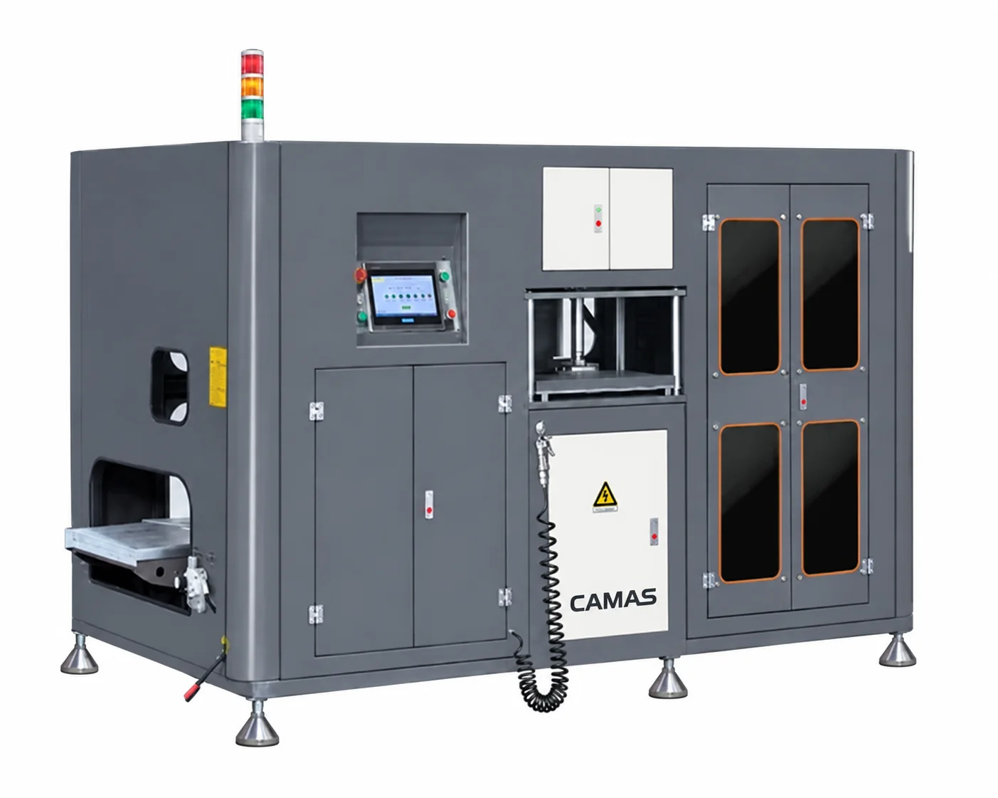
Industrial aluminum machining starts with the finished component. Connect its cut lengths, holes and milled features to practical stock handling and repeatable fixturing.
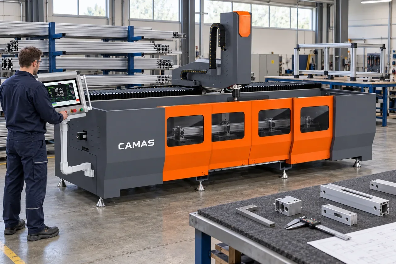
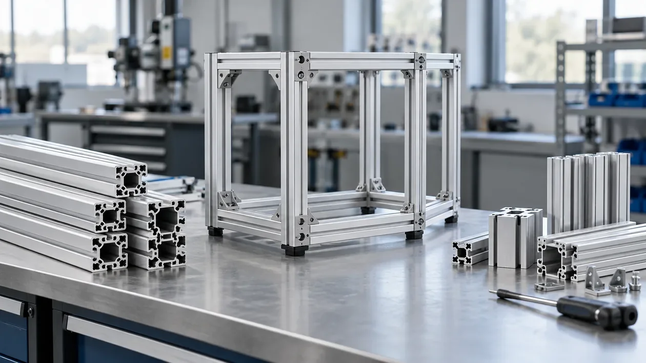
Component machining: profile blanks are organized by job, with finished parts checked at a separate bench.AI-generated application scene.
Typical end-use illustration.
WHAT YOUR CUSTOMERS MAKE
From extrusion to functional component.
Machine frames and equipment supports
Cut profile members and prepare specified fixing holes or mating ends. The assembly drawing determines where features belong and which surfaces matter.
Guards, enclosures and mounting members
Slots and drilled features locate panels, brackets or accessories. Review face access, clamp marks and the required surface finish.
Curved frames and shaped members
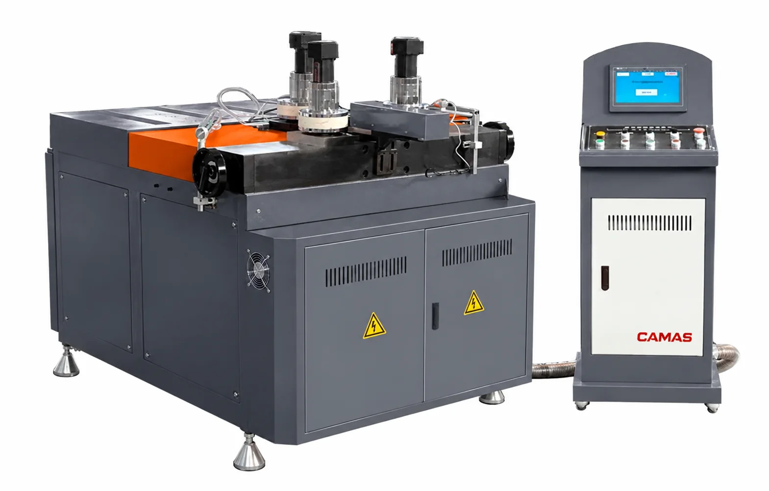
Add roll bending only when the design calls for a curve. The section, material and finished shape require a separate forming review.
FROM STOCK TO FINISHED PART
How the production stages connect.
01
Prepare blanks
Cut stock to the blank lengths needed for the next operation. Review the section, feed requirements and part mix for batch cutting.
Review
Blank length, cut condition and stock support.
02
Drill and mill features
Machine the functional holes, slots and pockets shown on the part drawing. Plan fixtures around the faces that must remain accessible.
Review
Feature positions, datums and face access.
03
Finish ends or form curves
Use end milling for the required end geometry. If the part needs a curve, review roll bending as a separate process with its own tools and limits.
Review
End geometry or finished curve requirements.
04
Inspect the component
Check critical features and the assembly fit. Organize inspection around the part drawing and the surfaces that locate the component.
Review
Critical dimensions, finish and mating fit.
BEFORE CHOOSING EQUIPMENT
Check the details that change the setup.
Choose by features
A profile length does not describe the entire machining task. Include hole depths, slots, pockets, machining faces and critical tolerances.
Account for the batch mix
Repeated parts and frequent changeovers have different setup needs. Include typical lot size, number of variants and the work your existing equipment already covers.
Keep forming separate
Do not infer a bending limit from a saw or machining-center specification. Review section deformation, tooling and the required final shape with the forming equipment.
ILLUSTRATIVE SELECTION EXAMPLE
Match blank preparation to the finished features
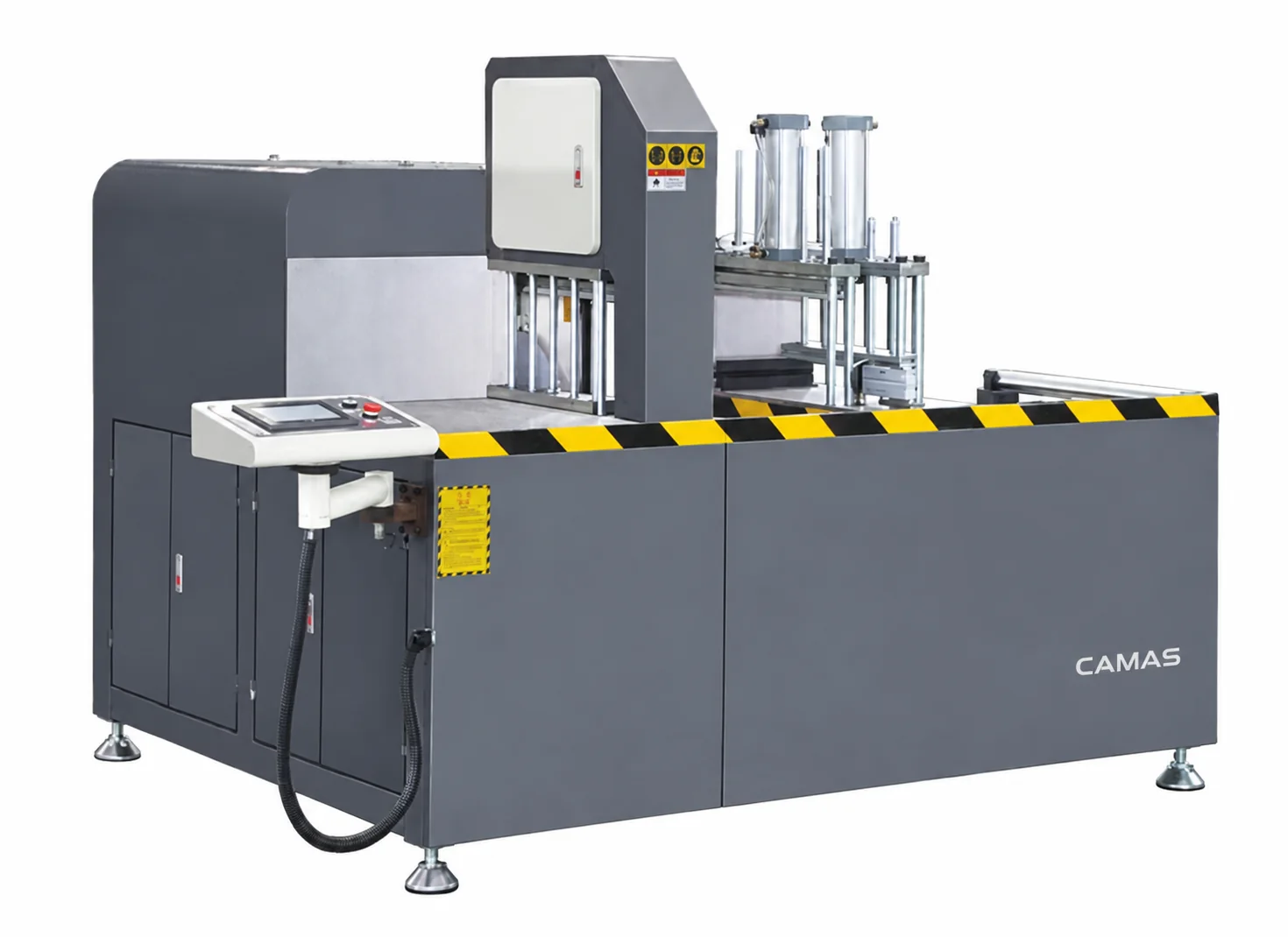
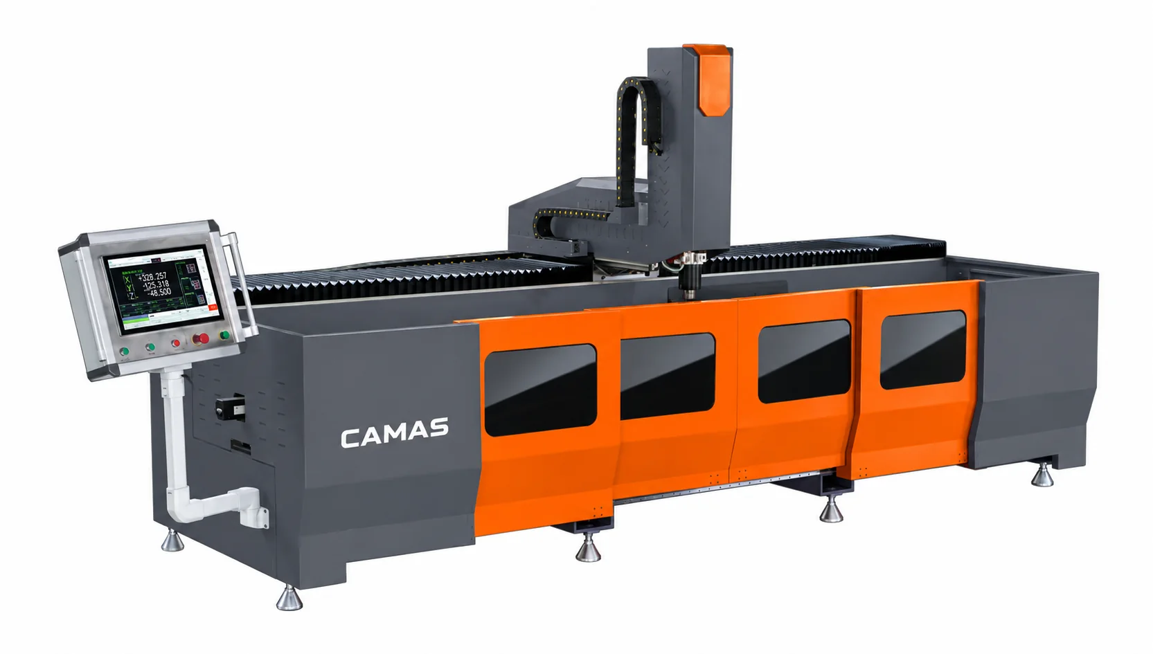
The JMG-CNC-450×500 publishes an auto-feed length of 5–580 mm (customizable); the LGS3Z-CNC-4000 publishes 4,000 mm X-axis travel. These describe different stages and should not be treated as one production-line length rating.
Map the job: cut blanks → drill and mill functional features → prepare mating ends → inspect critical assembly dimensions.
Check the cutting section separately from the machining clamps, tool access and faces on the finished-part drawing.
Add roll bending only when the part needs a curve; review the section and required final shape for that separate process.
Use this example to frame your inquiry. Confirm the finished drawing, machine configuration and tools before selecting equipment.
This application focuses on profile and extrusion processing. Review the component drawing to establish whether the operation, workholding and tools fit the proposed equipment.
Should I choose three axes or four?
Begin with the machining faces and features. Axis count alone does not describe clamp access, tooling or the number of setups needed for your component.
Can I add a machine to an existing line?
Yes, start with the operation you need to add. Share the incoming blank, completed part and upstream/downstream setup so handling and inspection stay connected.
START WITH YOUR PART
Let’s review your production task.
Send a representative drawing and the most demanding part in your range.