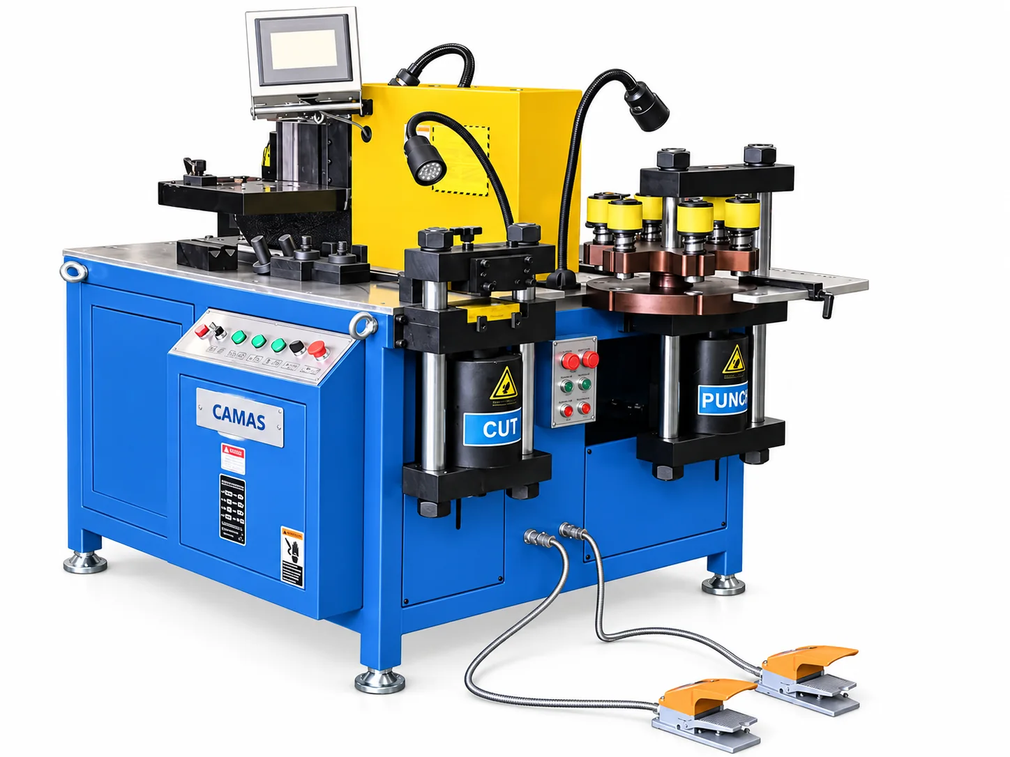
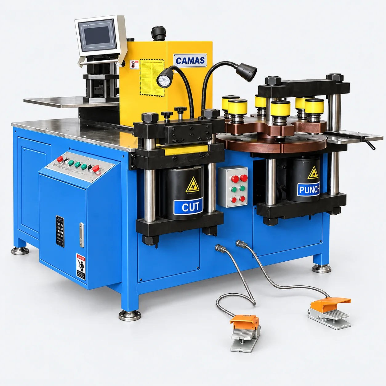
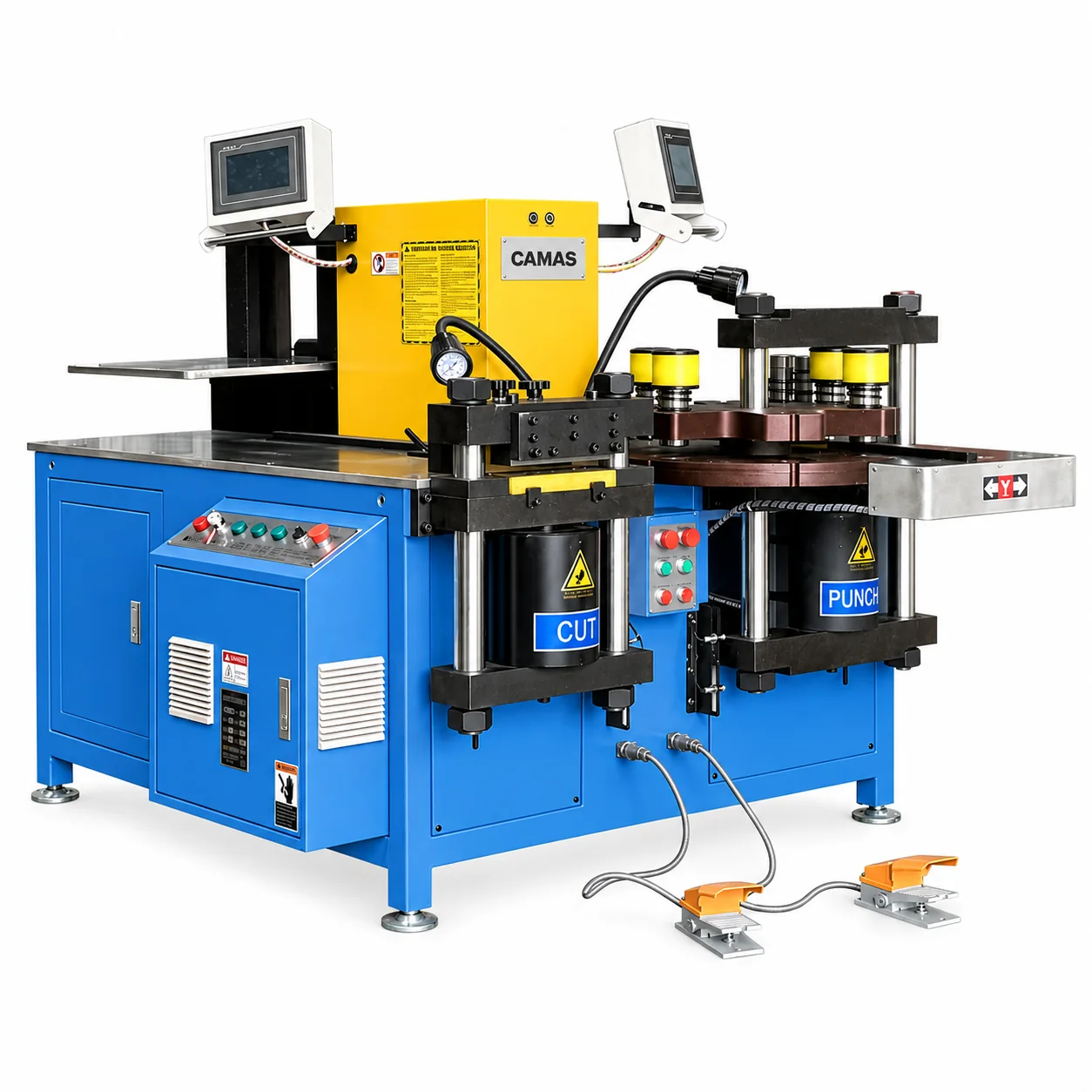
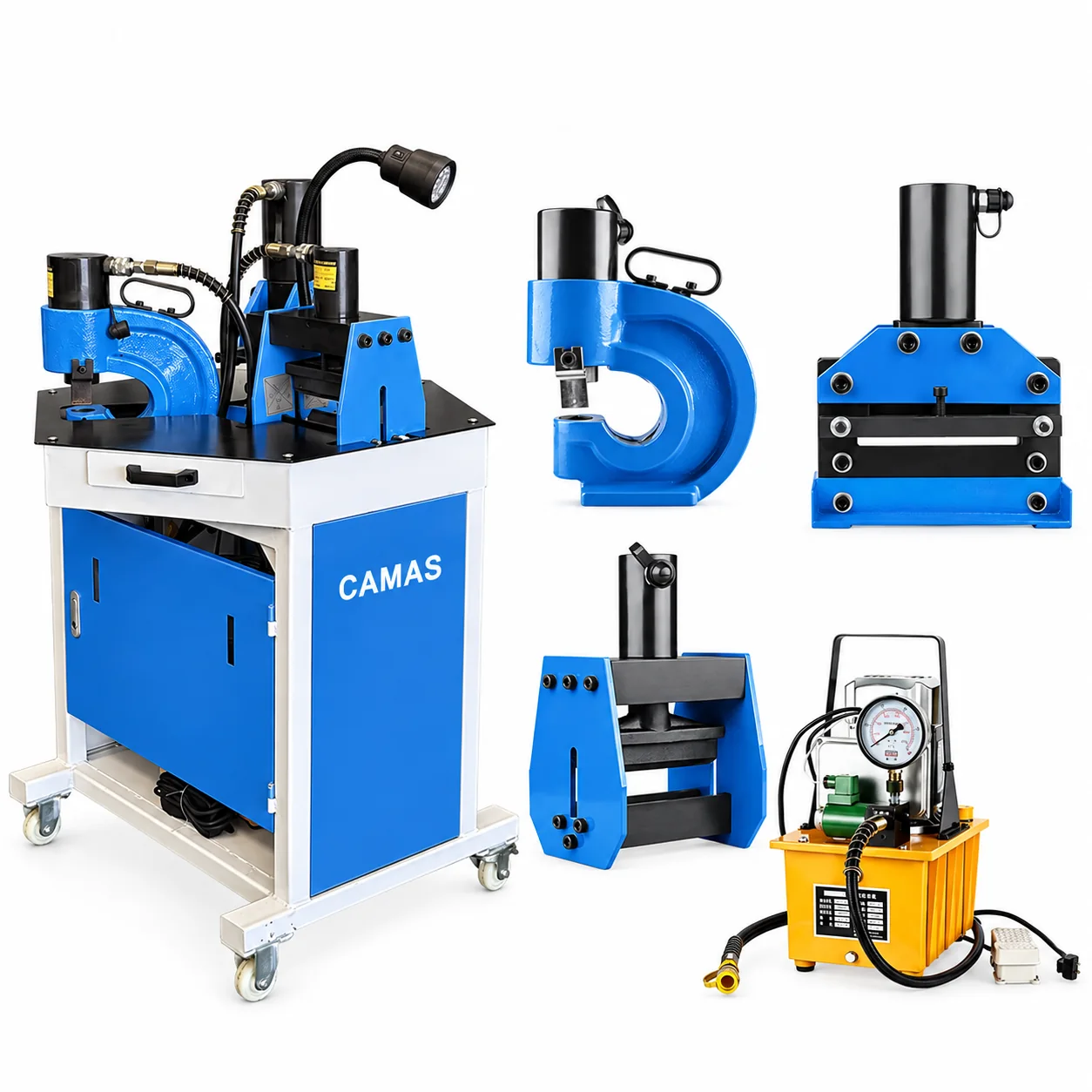
Busbar processing equipment for switchgear and panels.
Switchgear busbar processing turns copper or aluminum stock into electrical connections. Plan cut lengths, hole patterns and bends around the layout and clearances of your panel.
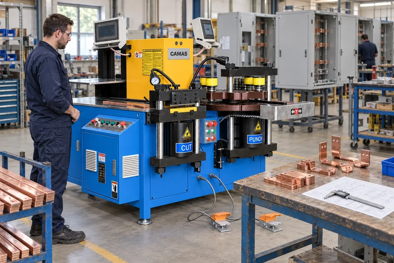
Busbar fabrication station: cutting, punching and bending are organized around the connection drawing and an inspection bench.AI-generated application scene.
Typical end-use illustration.
WHAT YOUR CUSTOMERS MAKE
Fabricate the connection your panel needs.
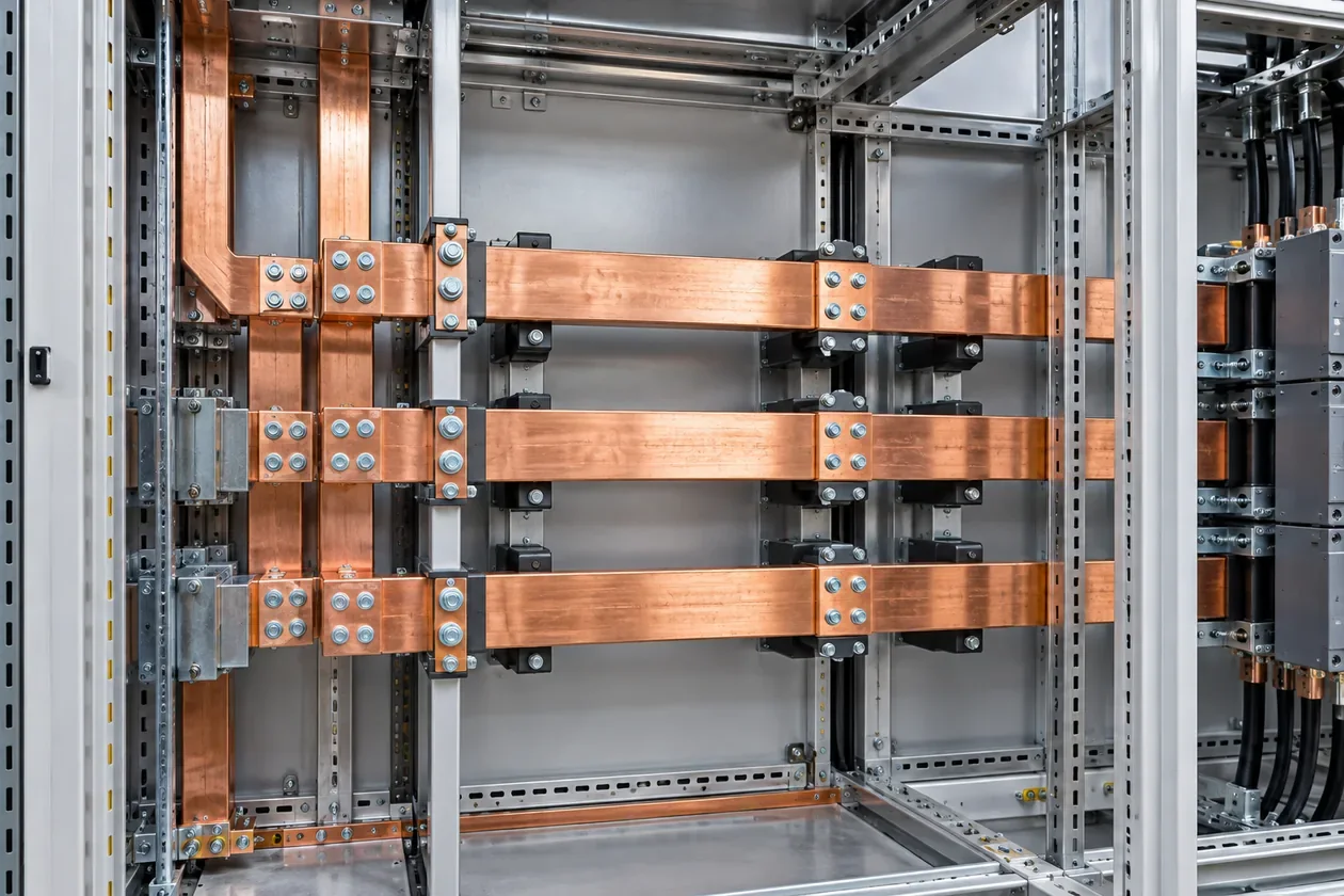
Cabinet distribution bars
Prepare bar lengths and fixing patterns for the specified layout. Stock width and thickness must be checked separately for each operation.
Device and terminal connections
Holes and offsets align the connection with its mounting points. Review hole size, pitch, edge distance and the bend geometry together.
Small batches and changing projects
Different panel layouts create different connection parts. Compare standard and servo positioning around the drawings and the manual handling between stations.
FROM STOCK TO FINISHED PART
How the production stages connect.
01
Cut the blank
Prepare the required length from the specified bar stock. Select the cutting method against the material and operation-specific range.
Review
Material, thickness, width and blank length.
02
Punch the fixing pattern
Match punch and die sizes to the drawing. Locate the holes from the specified datum before the connection is formed.
Review
Hole size, pitch, edge distance and tooling.
03
Form the connection
Bend the bar to the required offset or angle. Review flat versus edge bending and clearance around previously formed features.
Review
Bend direction, radius and part clearance.
04
Check before assembly
Check hole locations and formed geometry against the drawing, then confirm fit in the intended assembly.
Review
Dimensions, bend geometry and fit.
BEFORE CHOOSING EQUIPMENT
Check the details that change the setup.
Capacity by operation
A headline thickness × width is a starting reference. Cutting, punching, flat bending and edge bending can have different limits and tooling conditions.
Positioning versus handling
Servo positioning changes the positioning method; it does not mean automatic transfer between all stations. Include handling and setup in your comparison.
Fabrication versus electrical design
The machine processes the bar. Material selection, current rating, insulation and finished-panel acceptance remain part of the electrical design and verification.
ILLUSTRATIVE SELECTION EXAMPLE
Compare capacity and positioning as separate choices
The 30-3NC has a published 12 × 160 mm range; the 50-3NC and 50-3NC PRO share a published 16 × 250 mm range. The PRO adds servo positioning; it does not increase that headline size.
Map the connection: cutting blank → punching fixing pattern → bending assembly shape → checking the drawing dimensions.
Check punching diameter, edge distance and flat or edge bending separately; the headline stock size does not establish every feature limit.
Compare standard and servo positioning with the same connection drawing and part mix, including manual handling between stations.
Use this example to frame your inquiry. Confirm the finished drawing, machine configuration and tools before selecting equipment.
Compare both on the same connection drawings, batch sizes and part mix. Review the positioning workflow and operator handling rather than assuming a higher stock capacity.
Can one workstation cut, punch and bend?
The 3-in-1 models provide those stations. Confirm each operation’s range and the punch, die and bend tools required for your parts.
What helps avoid the wrong setup?
Send the material grade, maximum stock thickness and width, full hole pattern and all bend views. Include the tightest clearance and most demanding part.
START WITH YOUR PART
Let’s review your production task.
Send a representative drawing and the most demanding part in your range.