Final configuration and tooling are matched to your application.
01 / THE APPLICATION
Punching features with matched dies
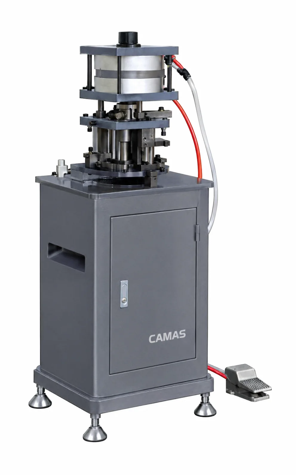
Punch hardware mounting features and slots with dedicated tooling.
Define each slot or hardware feature with its location and surrounding profile walls. Check the die interface, workpiece clearance and process-specific force and stroke.
Punching
Hardware installation features
Application-led configuration
Define your tools and working requirements from the component drawing.
02 / TECHNICAL OVERVIEW
LY-30 specifications
CAMAS LY-30 technical specifications
Equipment line
Aluminum Profile Machinery
Model
CAMAS LY-30
Nominal force
30 kN
Stations
5
Punching stroke
30 mm
Die space
340 × 240 × 500 mm
Machine weight
Approx. 160 kg
Process
Punching
Specifications support preliminary selection. Capacity varies with profile geometry, cutting angle, tooling and clamping. Values marked “to be confirmed” are not published in the source data. Confirm the supplied configuration in your quotation.
Published model data and the checks to resolve in your quotation.
Published machine configuration
Punch hardware mounting features and slots with dedicated tooling.
Configuration details
Stations: 5 · Nominal force: 30 kN · Die space: 340 × 240 × 500 mm
Tooling to define in your quotation
Itemize each die by feature size and shape. Confirm its interface, clearance and compatibility with the material and surrounding profile walls.
Supply and site requirements
State voltage, phase and frequency, control requirements and destination. Ask the quotation to distinguish included equipment, options, packing, documentation and installation or training arrangements.
What to include with your drawing
Profile section, material and stock length
Finished-part drawing, angles and critical dimensions
Production quantity and current process
Electrical supply, tooling and workshop requirements
For a machine review, include the sample operation, critical feature and finish you want to check. Ask CAMAS for model-specific footage or sample details when requesting your configuration.
Are the punching dies defined by the machine model?
The machine model alone does not define the tooling for your feature. Supply the profile section and finished hole or slot drawing so the quote can identify the required dies and their interface.
How do I know this configuration fits my part?
Send the finished-part drawing, material, dimensions and quantity. Review tooling access, working capacity and handling together before selecting the configuration.
What tools are included?
The agreed quotation defines the supplied blades, dies, cutters, gauges and accessories. Include your required holes, angles and features so the tool package can be itemized.
Can I specify the electrical supply?
Include voltage, phase and frequency in your inquiry. Electrical variations and control requirements should be confirmed for the specific configuration.
How are delivery and support arranged?
Delivery timing, packing, installation, training and spare-parts scope are agreed for the project. Share the destination and your site requirements when requesting a quotation.