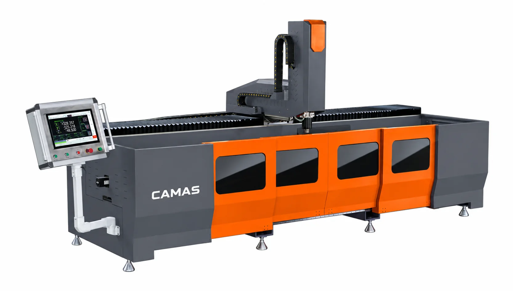
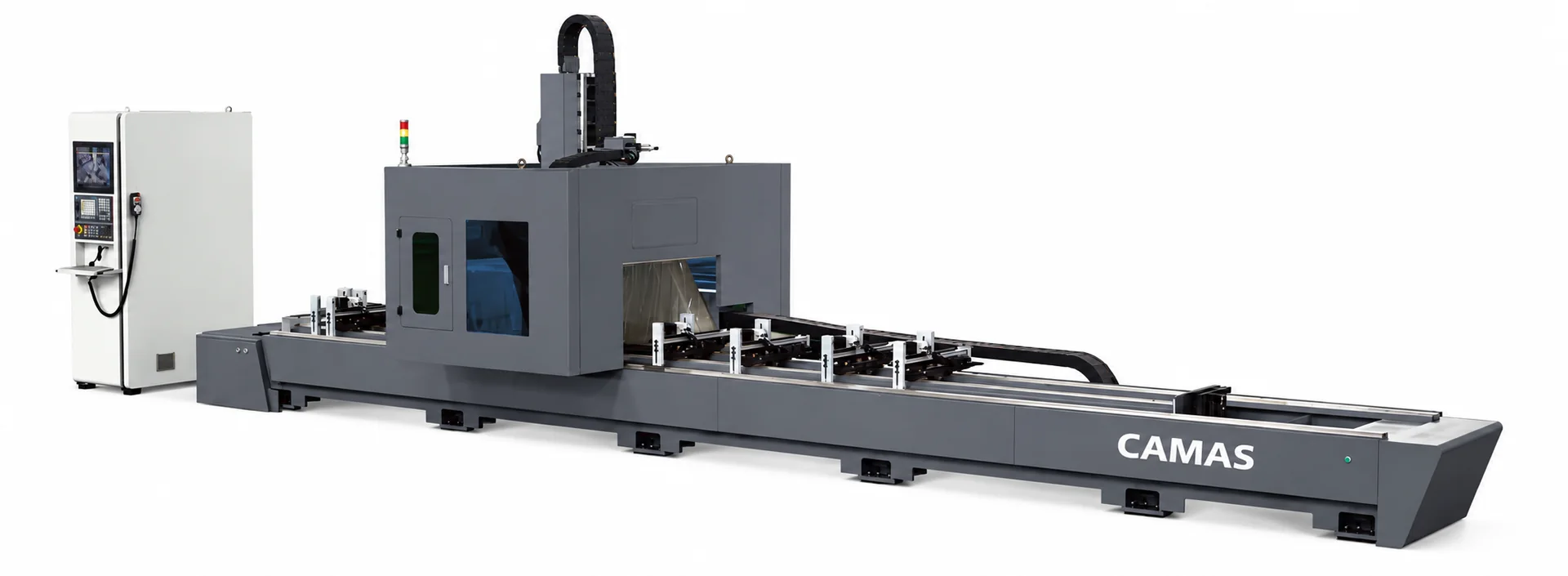
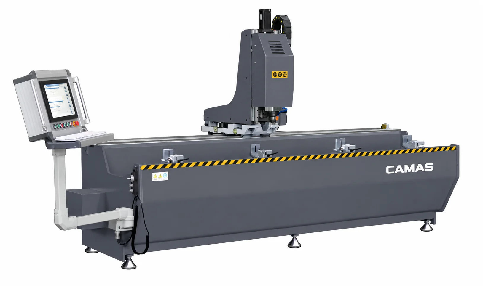
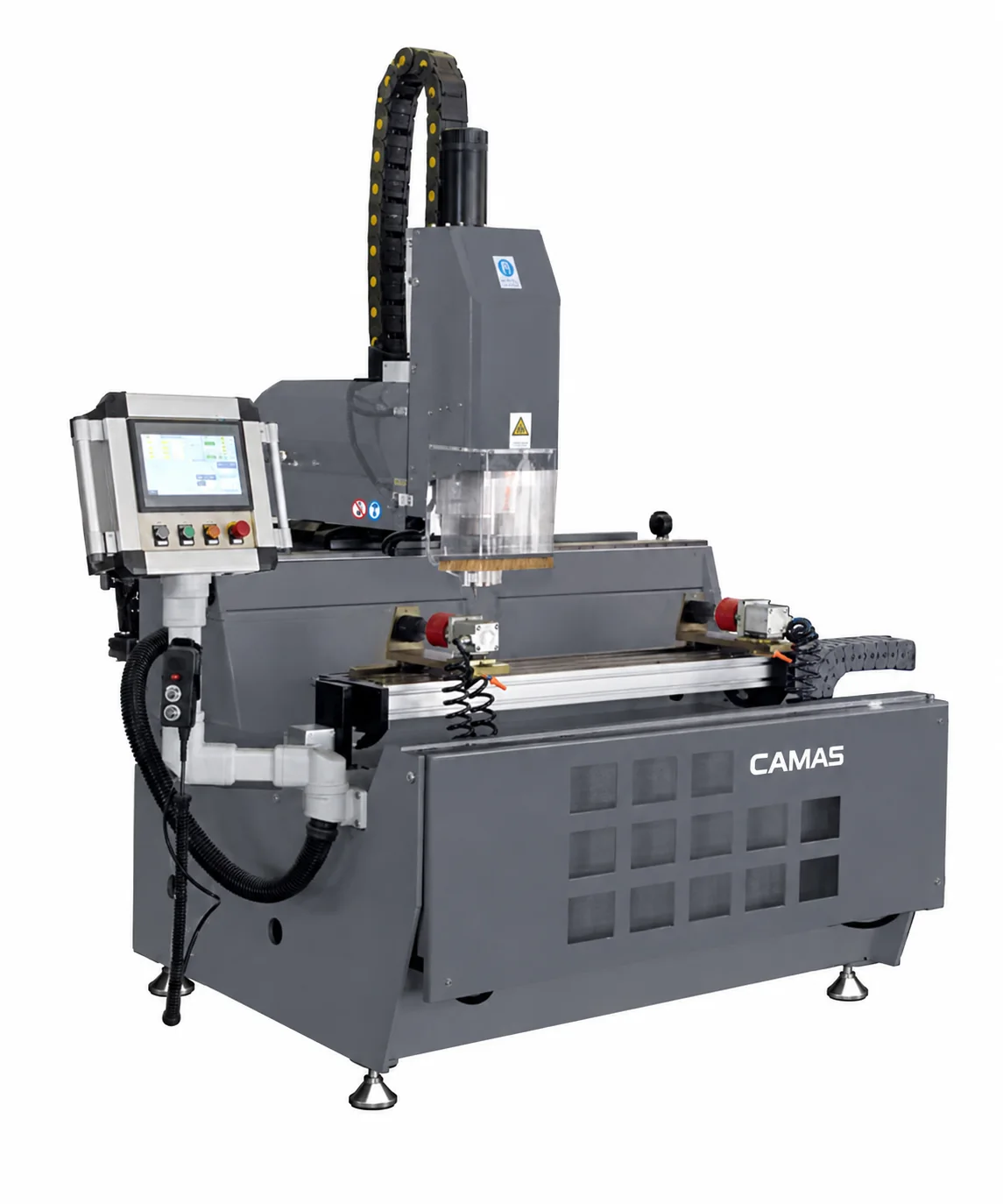
Final configuration and tooling are matched to your application.
01 / THE APPLICATION
Profile machining faces and tool access
High-speed drilling and milling for thick- and thin-wall aluminum profiles.
Identify the holes, slots and end features on each face of the extrusion. Review tool access, clamp positions and usable machining space. X/Y/Z travel describes machine motion and does not alone establish the part envelope.
CNC machining
3 axes · 4,000 mm X travel
Application-led configuration
Define your tools and working requirements from the component drawing.
02 / TECHNICAL OVERVIEW
LGS3Z-CNC-4000 specifications
CAMAS LGS3Z-CNC-4000 technical specifications
Equipment line
Aluminum Profile Machinery
Model
CAMAS LGS3Z-CNC-4000
Axes
3
X-axis travel
4,000 mm
Y-axis travel
640 mm
Z-axis travel
440 mm
Spindle power
9.6 kW (S6) / 8.0 kW (S1)
Maximum spindle speed
24,000 rpm
Tool magazine
6 stations
Repeat positioning accuracy
±0.02 mm
Machine weight
Approx. 2,100 kg
Process
CNC machining
Specifications support preliminary selection. Capacity varies with profile geometry, cutting angle, tooling and clamping. Values marked “to be confirmed” are not published in the source data. Confirm the supplied configuration in your quotation.
Published model data and the checks to resolve in your quotation.
Published machine configuration
High-speed drilling and milling for thick- and thin-wall aluminum profiles.
Configuration details
Axes: 3 · Tool magazine: 6 stations
Tooling to define in your quotation
List the cutters, tool holders, clamp layout and machining faces. Confirm the control/software package and the required drawing or program formats.
Supply and site requirements
State voltage, phase and frequency, control requirements and destination. Ask the quotation to distinguish included equipment, options, packing, documentation and installation or training arrangements.
What to include with your drawing
Profile section, material and stock length
Finished-part drawing, angles and critical dimensions
Production quantity and current process
Electrical supply, tooling and workshop requirements
For a machine review, include the sample operation, critical feature and finish you want to check. Ask CAMAS for model-specific footage or sample details when requesting your configuration.
Does axis travel equal the usable machining length?
No. Tool clearance, clamp positions, profile section and the faces being machined affect the usable range. Send the cross-section and finished-part drawing so the actual setup can be checked.
How do I know this configuration fits my part?
Send the finished-part drawing, material, dimensions and quantity. Review tooling access, working capacity and handling together before selecting the configuration.
What tools are included?
The agreed quotation defines the supplied blades, dies, cutters, gauges and accessories. Include your required holes, angles and features so the tool package can be itemized.
Can I specify the electrical supply?
Include voltage, phase and frequency in your inquiry. Electrical variations and control requirements should be confirmed for the specific configuration.
How are delivery and support arranged?
Delivery timing, packing, installation, training and spare-parts scope are agreed for the project. Share the destination and your site requirements when requesting a quotation.