Window and door machinery connects accurate profile cutting, hardware machining and frame assembly. Plan the sequence around the profiles and fittings you actually use.
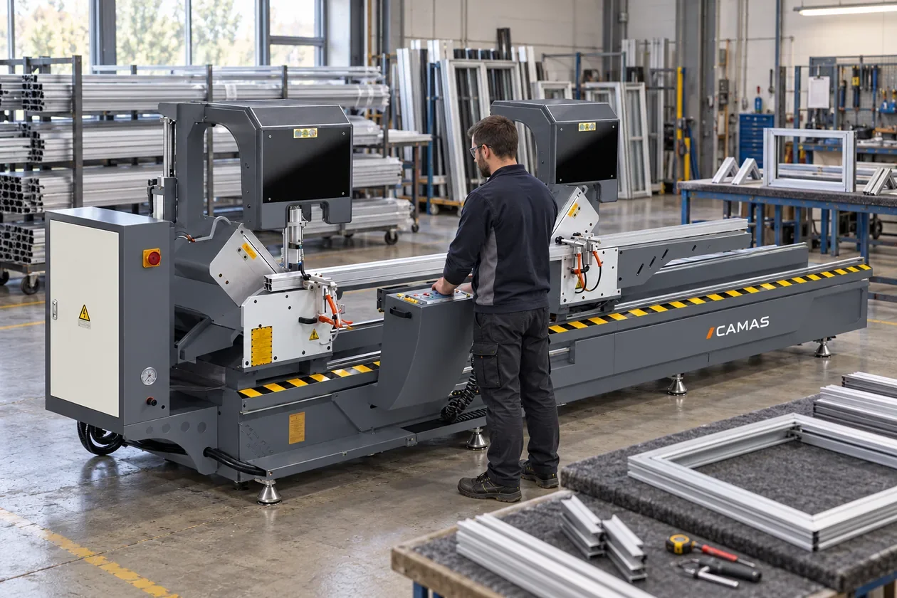
Profile cutting station: long stock is supported along the machine, with frame assembly organized downstream.AI-generated application scene.
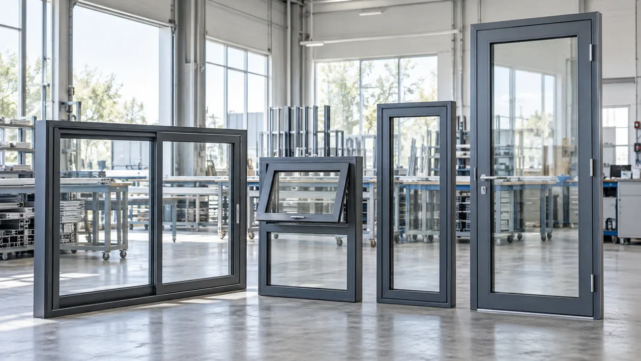
Typical end-use illustration.
WHAT YOUR CUSTOMERS MAKE
Different frames. A connected process.
Window frames and sashes
Mitre cuts define the frame geometry. Hardware holes, drainage slots and corner connectors then determine the machining and joining stages.
Door frames and larger openings
Longer members and larger sections change the cutting envelope and handling needs. Check the actual section at the required angle before choosing a saw.
Mullions and transoms
End faces must mate with the adjoining frame profile. Review both sections together so the end-milling tools and fixture match the joint.
FROM STOCK TO FINISHED PART
How the production stages connect.
01
Cut and identify profiles
Cut frame and sash members to the drawing length and mitre angle. Keep each set identified for the next workstation.
Review
Length, angle and the section envelope at 45° / 90°.
02
Machine hardware features
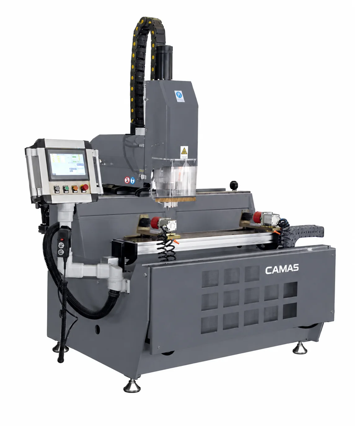
Drill and mill the specified lock, hinge, handle and drainage features. Check access to each face against the profile and clamps.
Review
Hole positions, slot geometry and visible surfaces.
03
Prepare mating ends
End-mill the members that join into another section. This stage applies to the joint design; every member does not require the same operation.
Review
Fit between both mating profile sections.
04
Join and inspect the frame
Crimp compatible corner-cleat joints, then check the assembled frame against the system drawing before downstream fitting.
Review
Corner alignment, joint fit and frame diagonals.
BEFORE CHOOSING EQUIPMENT
Check the details that change the setup.
Profile system first
Supply the frame, sash and mating-section drawings. Overall frame dimensions alone cannot establish whether the section fits the cutter, clamps or crimping knives.
Balance the workstations
Use your expected part mix and frames per shift to review cutting, machining, handling and assembly together. A saw specification alone cannot establish complete-line output.
Match the joint
Confirm cleat geometry, profile height, end-milling tools and crimping knife contact. Specify tools in the quotation rather than assuming a standard set suits every system.
ILLUSTRATIVE SELECTION EXAMPLE
Check the frame cut at the required angle
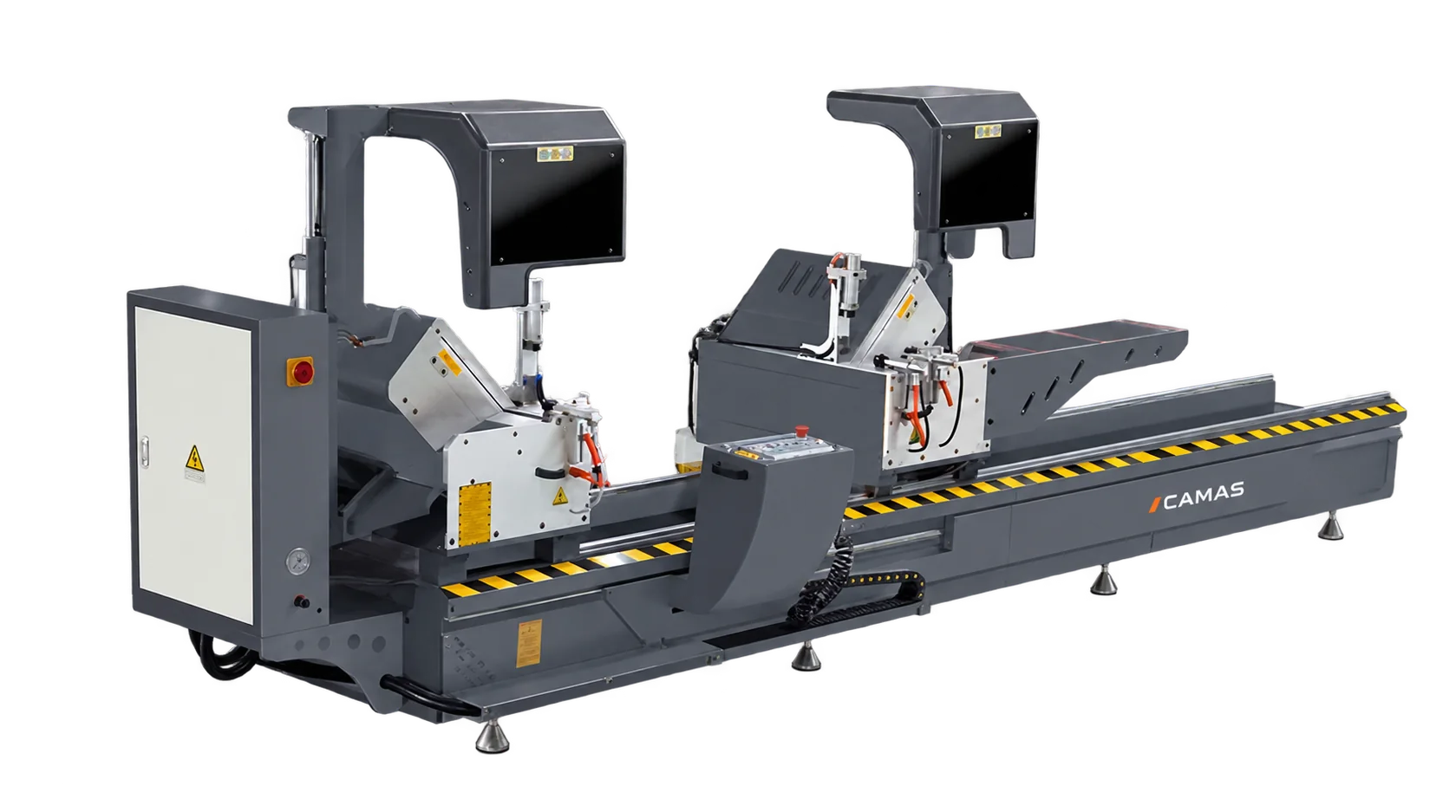
For the LJZ2-CNC-550×4500, the published cutting height is 200 mm at 45° / 230 mm at 90°. The larger 90° height is not the selection limit for a 45° frame cut.
Check profile width and height at every required angle, plus the shortest and longest finished lengths.
Map the job: saw for length and angle → machining for hardware features → end milling for the mating joint → crimping for compatible corner connectors.
Keep frame size and expected frames per shift in the brief; confirm the complete workflow rather than inferring output from one machine.
Use this example to frame your inquiry. Confirm the finished drawing, machine configuration and tools before selecting equipment.
No. Your profile system and finished drawing determine the operations. Begin with the parts you make, then identify which stages are needed and which your workshop already covers.
Can one setup handle several profile systems?
Review the largest and smallest sections, face access, mating joints and changeover requirements. Fixtures and tools may need to change between systems.
What should I send for selection?
Send representative section and frame drawings, cutting angles, hardware features and expected output. Include your most demanding profile as well as the everyday work.
START WITH YOUR PART
Let’s review your production task.
Send a representative drawing and the most demanding part in your range.