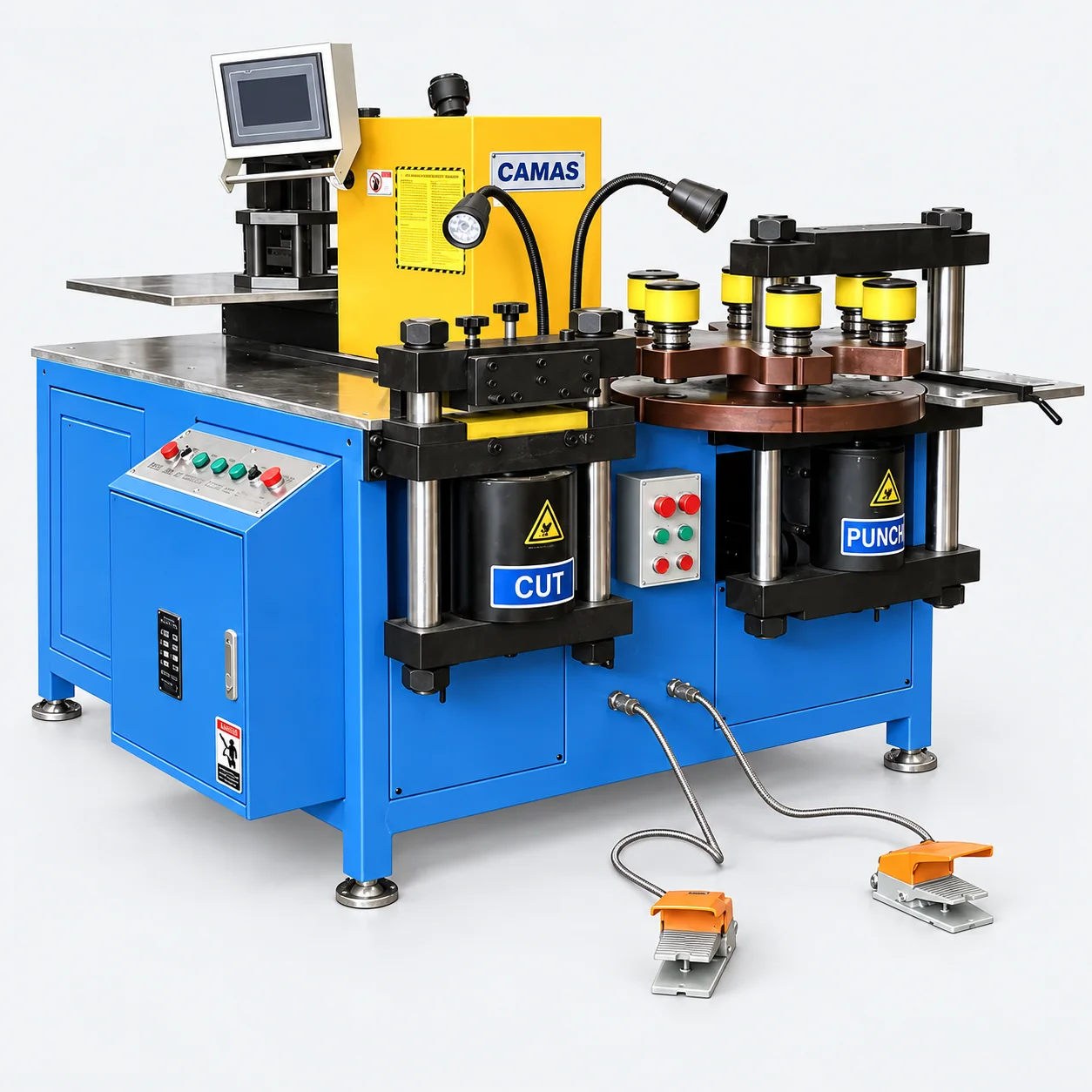
Busduct connection bar bending and forming equipment.
Busduct connection bars need the correct hole positions, bend directions and interface dimensions. Review the full part drawing before selecting processing equipment.
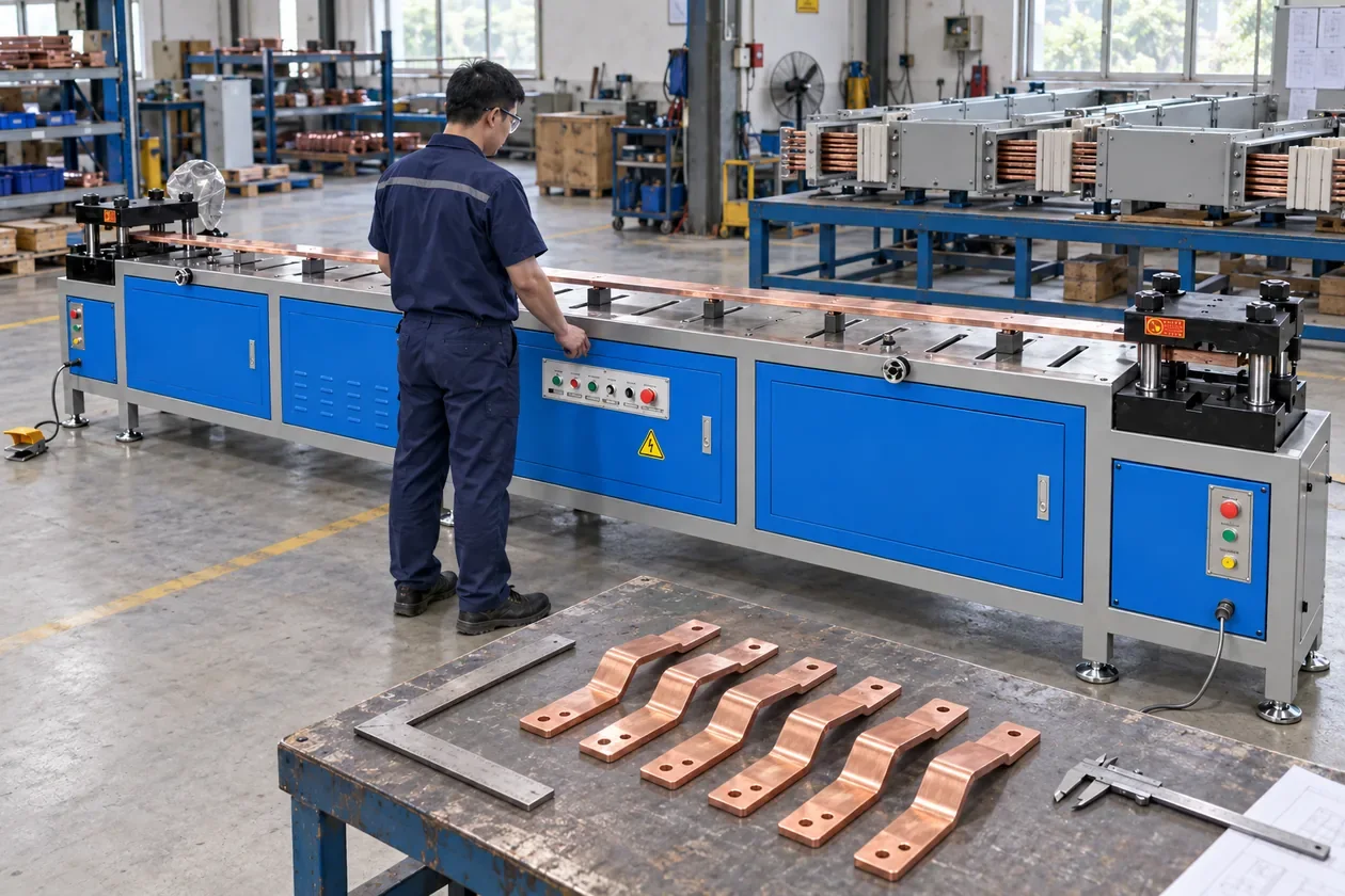
Connection-end forming: the bar is supported between the tools, with completed parts checked against the assembly geometry.AI-generated application scene.
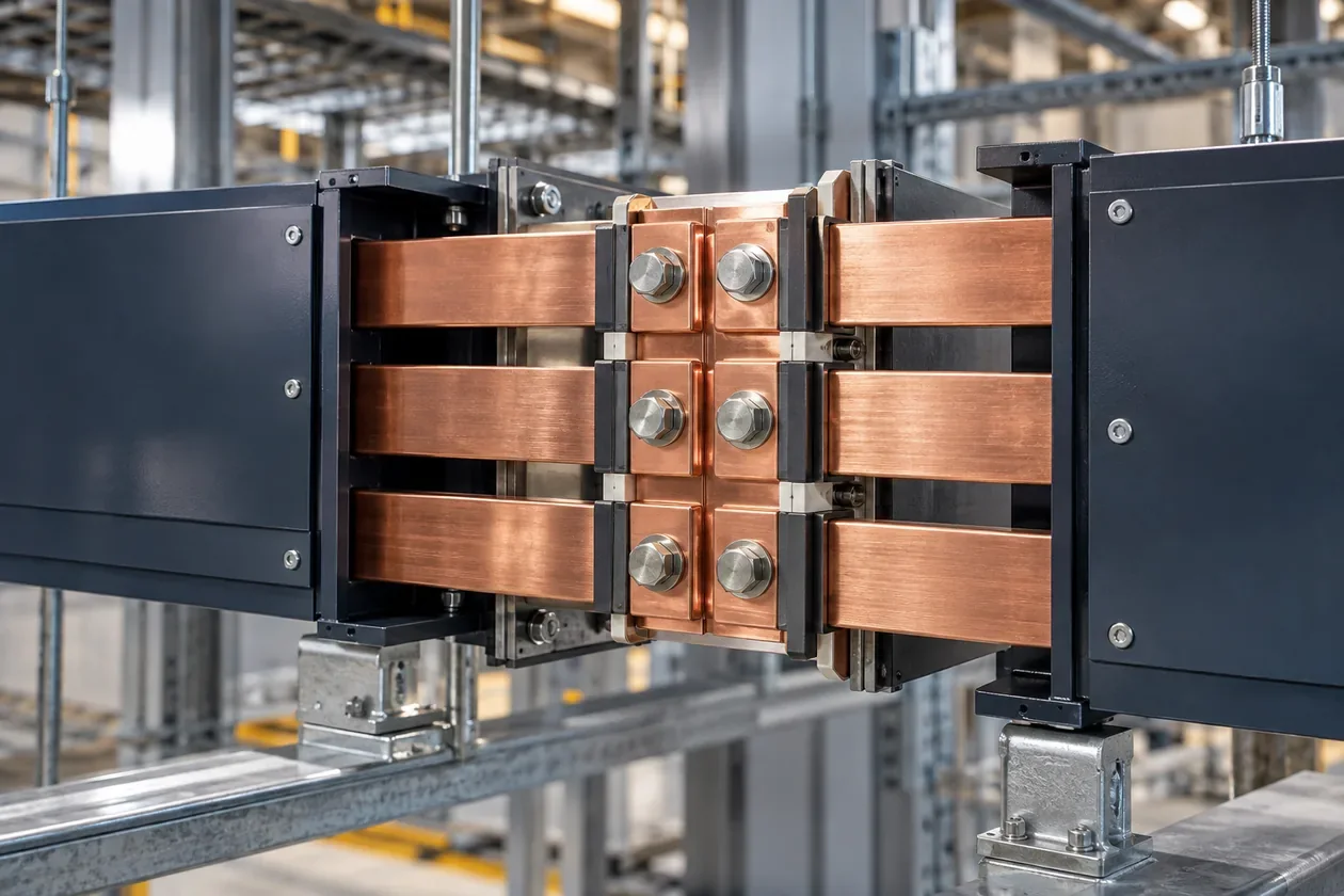
Typical end-use illustration.
WHAT YOUR CUSTOMERS MAKE
Connection geometry drives the forming setup.
Repeated connection ends
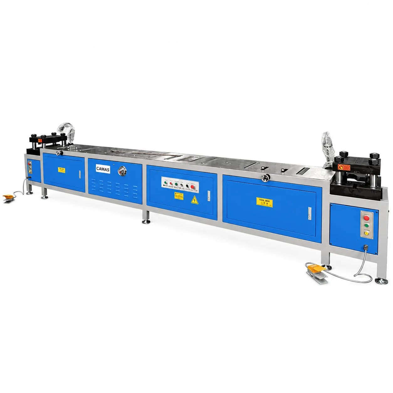
Where the design calls for repeated end forms, review the double-head forming method against the complete connector drawing and die geometry.
Offset and multi-bend connectors
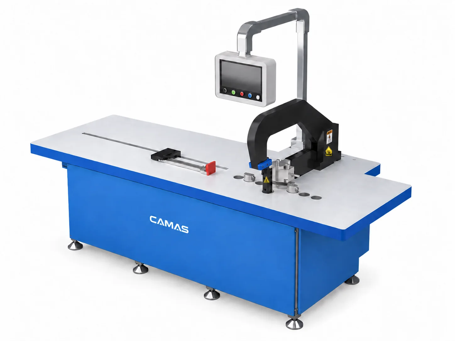
Several bends create clearance and sequence questions. Compare a CNC bending setup against the full part shape, including existing bends.
Punched connection assemblies
Hole centers and formed ends must align with the intended connection. Review the blank, punching pattern and final geometry as one part.
FROM STOCK TO FINISHED PART
How the production stages connect.
01
Review the complete part
Define the material, stock section, both end shapes and center distances. Include all views that show offsets and clearance.
Review
Drawing revision, end geometry and datums.
02
Choose the forming method
Compare double-head end forming with CNC bending according to the part. Similar stock dimensions do not make the methods interchangeable.
Review
End tools, direction and forming sequence.
03
Coordinate blank and holes
Review cutting and punching alongside forming. Determine the blank and hole positions from the agreed process for the finished connection.
Review
Blank length, fixing holes and process order.
04
Check spacing and fit
Inspect formed geometry and connection spacing. Trial-fit a representative part to the intended assembly when the project requires it.
Review
End spacing, hole alignment and assembly fit.
BEFORE CHOOSING EQUIPMENT
Check the details that change the setup.
Match the dies
End forms depend on the connector geometry and forming tools. Ask the quotation to identify the dies, adjustment scope and sample review required.
Review existing bends
A nominal stock size does not establish whether a finished offset will clear the tooling. Supply the complete part rather than a single flat-bar view.
Keep component scope clear
These machines address metal connection-bar fabrication. Busway housing, insulation and electrical system qualification require their own equipment and specifications.
ILLUSTRATIVE SELECTION EXAMPLE
Choose the forming method before comparing sizes
The 600B addresses double-head connection-end forming. The NC.40Z-2000 is a dedicated CNC bending configuration with a published 15 × 200 mm main range and a separate 12 × 120 mm vertical-bending range.
Provide the complete connection-end shape, spacing, stock size and previously formed features.
Review double-head end forming and angle bending as different processes; identify the tooling and datum needed for each.
Map cutting and hole preparation separately from the selected forming stage, then check the finished assembly fit.
Use this example to frame your inquiry. Confirm the finished drawing, machine configuration and tools before selecting equipment.
Review it when your connection drawing calls for the double-head end-forming method. Confirm both end shapes, stock section, spacing and the required dies.
When is CNC bending a better starting point?
Start that review for parts with repeat bend sequences or offsets that need the CNC bending method. Check full geometry, direction and tooling clearance against the proposed configuration.
What drawing should I provide?
Provide the finished connector with both ends, holes, bends, center distances and material. Include a representative part and the most demanding variant.
START WITH YOUR PART
Let’s review your production task.
Send a representative drawing and the most demanding part in your range.