Final configuration and tooling are matched to your application.
01 / THE APPLICATION
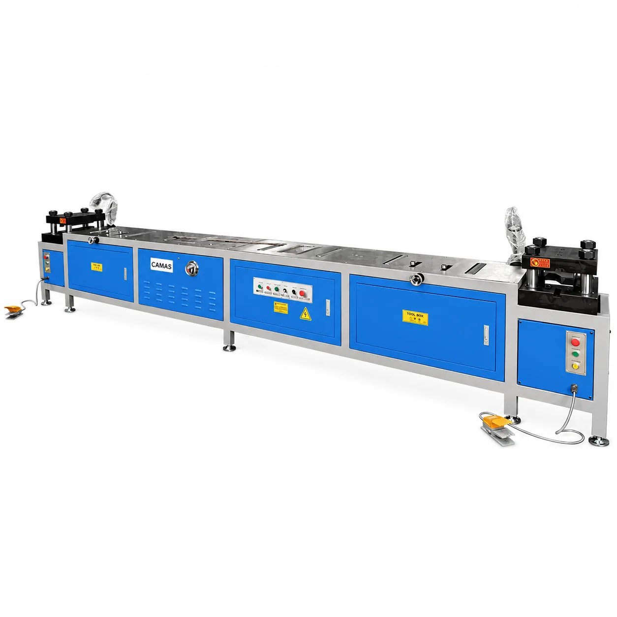
Double-head forming for busduct connection ends
Double-head forming for busduct connection bars and end shapes.
This configuration serves connection-bar end forming. Compare the complete end shape, tool arrangement, spacing and part support; do not assume it performs the same task as an NC.40Z angle-bending center.
Dedicated bending
Connection-bar forming
Application-led configuration
Define your tools and working requirements from the component drawing.
02 / TECHNICAL OVERVIEW
600B specifications
CAMAS 600B technical specifications
Equipment line
Busbar Processing Machinery
Model
CAMAS 600B
Thickness × width
3 × 30 to 6 × 200 mm
Machine weight
1300 kg
Motor power
4 kW
Machine dimensions (L × W × H)
3600 × 1000 × 1500 mm
Force
60 Ton
Control
Manual
Process
Dedicated bending
Specifications support preliminary selection. Material, hole size, edge distance, bend direction and tooling may impose separate limits. Confirm the supplied configuration in your quotation.
Published model data and the checks to resolve in your quotation.
Published machine configuration
Double-head forming for busduct connection bars and end shapes.
Configuration details
Control: Manual
Tooling to define in your quotation
Identify the dies, gauge reference, bend directions and part supports. Include existing bends and minimum flanges so the complete part can be checked.
Supply and site requirements
State voltage, phase and frequency, control requirements and destination. Ask the quotation to distinguish included equipment, options, packing, documentation and installation or training arrangements.
What to include with your drawing
Material grade, maximum thickness and width
Hole dimensions, bend direction and tooling requirements
Expected quantity and repeated dimensions
Electrical supply, destination and delivery requirements
For a machine review, include the sample operation, critical feature and finish you want to check. Ask CAMAS for model-specific footage or sample details when requesting your configuration.
Is double-head forming the same as CNC angle bending?
They address different forming tasks. Send the required connection end shape and dimensions so the forming method and tooling can be reviewed; compare the dedicated CNC bending range if your task requires angle and gauge positioning.
How do I know this configuration fits my part?
Send the finished-part drawing, material, dimensions and quantity. Review tooling access, working capacity and handling together before selecting the configuration.
What tools are included?
The agreed quotation defines the supplied blades, dies, cutters, gauges and accessories. Include your required holes, angles and features so the tool package can be itemized.
Can I specify the electrical supply?
Include voltage, phase and frequency in your inquiry. Electrical variations and control requirements should be confirmed for the specific configuration.
How are delivery and support arranged?
Delivery timing, packing, installation, training and spare-parts scope are agreed for the project. Share the destination and your site requirements when requesting a quotation.